An Electrical disconnect switch is necessary for most 240-Volt appliances according to electrical safety codes. The only devices which are exempted from this requirement are those that are in sight and within 50 feet of the breaker box. All appliances which are in another room or outside must have a disconnect switch close-by as a safety measure for electrical providers that may be required to work on the devices. The wiring for the disconnect switch is an essential connection on the circuit breaker cable to supply power to the appliances.
Step 1
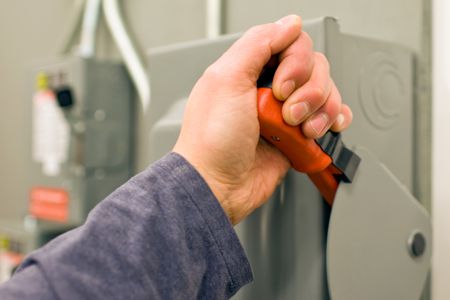
- The double breaker switch on the circuit that is running power to the appliance which needs an electrical disconnect switch must be shut off. A Warning label or lock must be placed on the breaker box to keep other switches from flipping the switch on again.
Step 2
- Next, the supply cable that provides power to the appliance must be cut if it is already wired. A utility knife can be used to slice through the outer jacket.
- Each separate wire must be clipped on the inside with wire cutters. Half an inch of the insulation must be stripped away with wire cutters, exposing ends of the black, red and white wires. Then an extra ten inch of white wire must subsequently be stripped in the same manner.
Step 3
- The panel’s cover plate and screws need to be removed from the electrical disconnect box.
- The cable end which is running from the home power supply must be pushed into a knockout of the disconnect switch’s wiring panel box.
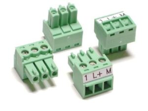
- The black and red wires need to be connected directly to the higher switch terminals marked “hot” or “line in”. Any wire can go on any terminal.
- The terminal screws must be loosened with a slotted screwdriver, and the bare conductors are pushed into the terminal slots, and the terminal screws tightened.
Step 4
- The white neutral wire must be connected from the cable to a screw terminal situated on the “line neutral” block, which will be visibly labeled on a GFCI disconnect switch that exhibits one.

- A white wire length must be run from a different terminal on the neutral line block to the center terminal which is situated in the row with three screw terminals on the bottom of the switch.
- The uninsulated copper ground wire must be connected to the marked ground terminal block.
Step 5
- The end of the cable running to the device must be pushed through a different knockout on the box.
- The red and black wires must then be connected to the outside two-screw terminals on the bottom end of the switch.
- Any color can be connected to either end.
- The white wire is then connected to the center terminal together with the other white wire length which is running from the neutral block.
- The ground wire must be connected to a terminal on the ground block, and the terminal screws tightened firmly.
Step 6
- The cover plate is then covered over the panel, and the holding screws tightened so that the disconnect switch can be installed.
- The power on the home breaker panel may be turned on, and the disconnect switch turned to transfer power to the appliance.
Looking for a reliable electrician in Perth?
Contact us today on (08) 9220 5201
Contact us today on (08) 9220 5201